
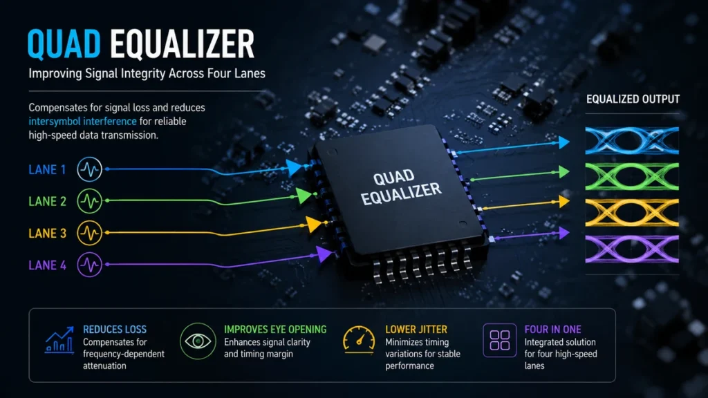
At multi-gigabit data rates, even an ordinary PCB trace or copper cable can become part of the problem. High-frequency components weaken as signals travel, edges become less distinct, and the receiver may eventually struggle to tell one bit from the next.
A quad equalizer addresses this problem across four signal lanes at the same time. Rather than treating four high-speed channels with separate devices, it integrates multiple receive equalization paths into one package, making it useful for multi-lane interfaces, backplanes, cables, and other high-speed serial links.
Quick answer: A quad equalizer is a four-channel signal-conditioning device designed to compensate for frequency-dependent losses in high-speed transmission paths. By applying equalization independently or programmably across four lanes, it can reduce intersymbol interference, improve eye opening, and help a receiver recover data reliably after signals travel through lossy PCB traces or copper cables.
What Is a Quad Equalizer?
The word quad refers to four channels or lanes. The word equalizer describes circuitry that compensates for the way a transmission medium changes a signal as it travels.
This is different from the familiar audio equalizer used to adjust bass, midrange, and treble. In high-speed electronics, equalization is primarily about signal integrity.
Copper traces and cables do not attenuate every frequency equally. At high data rates, higher-frequency signal components typically experience greater loss. The resulting waveform arriving at the receiver may have slower transitions and greater interference between neighboring bits.
A quad equalizer applies compensation to four channels, helping counter these channel losses before the data reaches downstream receiver circuitry.
For example, Texas Instruments describes its DS32EV400 as a programmable four-channel equalizer intended to compensate for transmission-medium loss and reduce deterministic jitter. The device supports operation up to 3.2 Gbps and provides eight programmable equalization levels.
The basic signal path can be viewed as:
Transmitter → PCB trace/cable → Quad equalizer → Receiver
The equalizer does not recreate missing data. Instead, it reshapes a degraded but recoverable signal so that the receiving system has a cleaner electrical waveform to interpret.
Why High-Speed Signals Need Equalization
At low data rates and over short connections, signal degradation may be small enough to ignore.
That changes as speeds increase.
Several effects become more significant.
Frequency-Dependent Channel Loss
PCB traces, connectors, vias, and cables attenuate signals. High-frequency components often suffer more attenuation than lower-frequency components.
Because fast digital edges contain high-frequency energy, losing these components causes edges to become slower and less distinct.
Intersymbol Interference
One of the most important problems is intersymbol interference, usually abbreviated as ISI.
A transmitted bit ideally occupies its own clearly defined time interval. After traveling through a lossy channel, however, the energy associated with one bit can spread into neighboring bit periods.
The receiver then sees overlapping symbols rather than clean transitions.
Receiver equalization is specifically used to compensate for this type of channel-induced degradation. Analog Devices, for example, states that its MAX3980 receiver equalization reduces ISI on four 3.125 Gbps differential data lanes.
Jitter
Jitter describes variations in the timing of signal transitions.
A receiver expects transitions within particular timing windows. Excessive jitter can move those transitions toward the edges of the valid sampling region and increase the chance of bit errors.
Some quad equalizers are therefore characterized not only by their loss compensation but also by their residual deterministic jitter.
Closed or Reduced Eye Diagrams
Engineers often evaluate high-speed digital signals with an eye diagram.
A healthy signal produces a relatively open eye. Loss, noise, ISI, and jitter gradually close that opening.
A smaller eye gives the receiver less voltage and timing margin.
Proper equalization can help reopen the eye by compensating for predictable channel loss.
How a Quad Equalizer Works
The core idea is selective compensation.
Suppose a PCB trace attenuates the high-frequency components of a signal more severely than the lower-frequency components. The equalizer can apply a frequency response that counteracts part of that attenuation.
The combined response becomes flatter:
Channel loss + equalizer compensation = improved receiver waveform
Real implementations are more sophisticated than this simplified description, but the principle explains why equalization works.
A quad device repeats the process across four lanes.
Depending on the IC, the four channels may include functions such as:
- receive equalization;
- limiting amplification;
- signal detection;
- programmable compensation;
- output drivers;
- channel enable or standby controls;
- serial-bus configuration.
The architecture varies considerably by device and application.
Texas Instruments’ DS64EV400, for instance, provides four data channels containing an equalizer stage, limiting amplifier, DC-offset correction circuitry, and a CML driver. It is designed for cable and backplane applications at rates up to 10 Gbps.
The Four Channels Are the Key Difference
Why integrate four equalizers instead of using one?
Many high-speed interfaces transmit data over multiple parallel serial lanes.
A four-lane architecture allows a designer to condition all four lanes with a single integrated component. That can simplify board layout and reduce component count compared with using four independent single-channel equalizers.
However, the lanes still need careful treatment.
Matching matters because excessive differences in propagation delay between lanes can create lane-to-lane skew. PCB routing, connectors, and package characteristics therefore remain important even when the equalization itself is integrated.
Some devices also allow each channel to be configured independently. This can be valuable when one physical lane experiences more loss than another because of differences in routing length or channel construction.
Programmable vs. Adaptive Equalization
Not every quad equalizer handles compensation in the same way.
Programmable Equalization
A programmable equalizer gives the designer several predefined compensation levels.
The appropriate setting depends on the expected channel loss.
For example, the DS32EV400 provides eight levels of programmable equalization, configurable through control pins or SMBus.
This approach gives engineers direct control over the receiver response.
It works especially well when the channel characteristics are reasonably predictable.
Adaptive Equalization
Adaptive equalization can automatically adjust its response according to the received signal or channel conditions.
This can be useful when cable lengths, insertion losses, or operating conditions vary.
Analog Devices’ MAX3980 is an example of a quad equalizer designed to adaptively support four XAUI lanes across FR4 backplane material.
Neither approach is universally superior.
Programmable equalization offers predictable control, while adaptive techniques can reduce the need for manual tuning in variable channels.
Quad Equalizer vs. Redriver
The terms equalizer and redriver are sometimes used together, but they do not describe exactly the same function.
An equalizer primarily compensates for channel loss at the receiving side.
A redriver typically combines receive-side signal conditioning with output circuitry that retransmits or reshapes the signal for another section of the channel.
A useful distinction is:
| Function | Quad Equalizer | Quad Equalizer/Redriver |
|---|---|---|
| Compensates for channel loss | Yes | Yes |
| Conditions four lanes | Yes | Yes |
| Provides a renewed output drive | Device-dependent | Typically yes |
| Output emphasis/de-emphasis | Not always | Often available |
| Used to extend practical channel reach | Yes | Yes |
| Best choice | Receiver-side compensation | Mid-channel or extended routing |
The MAX14950 illustrates the combined approach. It integrates four channels with programmable input equalization and output redrive circuitry for PCI Express applications. Analog Devices specifies support for PCIe Gen III at 8.0 GT/s, Gen II at 5.0 GT/s, and compatibility with Gen I at 2.5 GT/s.
The distinction matters when choosing a component. If the design simply needs to clean up a degraded signal near a receiver, an equalizer may be enough. If the conditioned signal must continue through another significant section of lossy interconnect, redrive capability can become important.
Where Quad Equalizers Are Used
Quad equalizers appear wherever four high-speed electrical lanes must survive challenging copper channels.
PCB Backplanes
Backplanes can contain long FR4 traces, connectors, vias, and other discontinuities.
At multi-gigabit rates, insertion loss through these paths can seriously degrade signal quality.
The MAX3980, for example, was designed around four 3.125 Gbps XAUI lanes and specified for operation across up to 40 inches of FR4 PCB material.
Copper Cables
Cable attenuation is another common application.
The MAX3981 was designed as a four-lane XAUI cable equalizer. Analog Devices specifies operation at 3.125 Gbps and support for up to 10 meters of twin-axial cable in its intended application.
Those figures should not be treated as universal quad-equalizer limits. Reach depends heavily on the particular IC, cable construction, data rate, connectors, and overall loss budget.
PCI Express
PCIe links are particularly sensitive to channel loss as data rates rise.
Equalizers and redrivers can be placed strategically between PCIe components when the native electrical channel becomes difficult to maintain.
The MAX14950 is one example designed specifically for PCIe signal-integrity improvement through receive equalization and redrive circuitry.
DisplayPort and Other Multi-Lane Links
Four-lane signal conditioning is also useful in display and high-speed interconnect applications.
Texas Instruments’ DS32EV400 is identified as a DisplayPort quad equalizer and supports four NRZ channels.
Renesas’ QLX4600-S30 is another example of a four-channel receive-side equalizer designed for protocols including DisplayPort, PCI Express, InfiniBand, and 10GBase-CX4, with line rates up to 6.25 Gb/s.
Storage and High-Speed Data Interfaces
Depending on the specific device, quad equalization can also appear around technologies such as:
- SAS;
- SATA;
- Fibre Channel;
- InfiniBand;
- XAUI;
- high-speed proprietary serial links.
The MAX3987, for example, supports four channels and is designed for receive equalization and preemphasis at speeds up to 8.5 Gbps. Its listed applications include PCIe-compatible links, XAUI, Fibre Channel, InfiniBand, SAS-2, and SATA Revision 3 OOB signaling.
Important Quad Equalizer Specifications
Selecting an equalizer by the number of channels alone is a mistake. Several electrical characteristics determine whether the component actually fits the link.
Maximum Data Rate
Start with the required lane speed.
Different quad equalizers target dramatically different generations of high-speed interfaces. Examples range from devices built around 3.125 Gbps XAUI links to components supporting approximately 8–10 Gbps operation.
A device’s headline data rate should never be the only selection criterion. Protocol requirements and the expected channel loss at relevant frequencies also matter.
Equalization Range
Equalization capability describes how much channel attenuation the receiver can compensate for under specified conditions.
More is not automatically better.
Too little compensation leaves the eye closed. Excessive equalization can amplify unwanted high-frequency noise and distort a channel that did not require that much correction.
This is why programmable devices provide multiple settings.
Input and Output Architecture
High-speed serial equalizers commonly use differential signaling.
Depending on the device, designers may encounter CML-style interfaces, integrated termination, AC coupling, DC coupling, or protocol-specific electrical requirements.
The MAX3980, for example, uses 100-ohm differential CML data inputs and outputs.
Compatibility must be verified from the actual datasheet rather than assumed from the term “quad equalizer.”
Jitter Performance
Equalization should improve the usable timing margin without introducing unacceptable additional jitter.
Look at specifications for deterministic jitter, random jitter, total jitter, and propagation delay where applicable.
These values become particularly important in systems operating close to the protocol’s signal-integrity limits.
Power Consumption
Four high-speed channels operating continuously can consume meaningful power.
Power matters for:
- dense servers;
- networking equipment;
- embedded systems;
- industrial electronics;
- thermally constrained boards.
Some devices therefore provide per-channel standby or power-down features so unused lanes do not remain fully active.
Configuration Interface
Configuration methods vary.
A device might use:
- external pins;
- DIP-switch-style hardware settings on an evaluation platform;
- SMBus;
- I²C;
- register-based software control.
For example, the MAX3987 allows parameters such as preemphasis, output drive, polarity, and unused-output power-down to be controlled through an I²C interface, with some global configuration also possible through pins.
Equalization and Preemphasis Are Not the Same Thing
These two concepts are closely related but act at different points.
Receive equalization compensates for degradation after the signal has traveled through a lossy channel.
Transmit preemphasis or de-emphasis modifies the transmitted waveform before it encounters that loss.
Some integrated devices combine both techniques.
The MAX3987 is a useful example because it combines four-channel receive equalization with programmable output preemphasis. Analog Devices says the device can be positioned at the beginning, middle, or end of a channel depending on the application.
A system designer may therefore use transmitter equalization, receiver equalization, or both as part of the overall link budget.
How to Choose the Right Equalization Setting
Using the strongest available setting is a common mistake.
Equalization should match the channel.
A practical process is:
- Estimate or measure channel insertion loss.
- Identify the relevant Nyquist frequency and operating data rate.
- Choose an initial compensation level appropriate for that loss.
- Measure the resulting eye diagram and jitter performance.
- Test nearby settings rather than assuming maximum compensation is best.
- Verify operation across voltage, temperature, cable, and board variations.
This matters because over-equalization can be just as undesirable as under-equalization.
If a short, low-loss trace receives aggressive high-frequency boost, noise can be emphasized unnecessarily.
The best setting is the one that produces adequate receiver margin for the actual channel.
Where Should a Quad Equalizer Be Placed?
Placement depends on the architecture of the device.
A receiver-oriented equalizer is generally most useful near the receiving endpoint because it compensates for the loss accumulated before the receiver.
For example, documentation for the DS50EV401 describes it as a unidirectional receiver intended for placement close to the link endpoint.
A redriver or combined equalizer/preemphasis device may be used differently because it can regenerate the output before another lossy section.
That makes placement a system-level decision involving:
- total trace length;
- connector position;
- cable length;
- channel insertion loss;
- transmitter capability;
- receiver capability;
- protocol compliance;
- available PCB space.
Simply placing an equalizer halfway along every long trace is not a reliable design rule.
Common Mistakes When Working With Quad Equalizers
The component can improve a difficult link, but it cannot rescue every poor PCB design.
Treating Equalization as a Fix for Bad Layout
Equalization does not eliminate the need for controlled impedance, appropriate stack-up, sensible via design, clean reference planes, and properly routed differential pairs.
The physical channel comes first.
Ignoring Connectors and Vias
Designers sometimes calculate only PCB trace loss.
In practice, connectors, vias, packages, and cables contribute to the complete channel response.
A short trace with several poor discontinuities can be more troublesome than a longer but carefully designed route.
Using Maximum Equalization by Default
More compensation does not automatically produce a better eye.
Tune for the real loss profile.
Looking Only at Data Rate
Two devices supporting the same nominal rate may have very different:
- compensation ranges;
- jitter characteristics;
- protocol features;
- electrical idle behavior;
- input/output architectures;
- configuration methods.
Data rate is only the starting filter.
Forgetting Device Lifecycle
This is especially important when researching older quad equalizer parts.
Several historically important devices are now obsolete or not recommended for new designs. Analog Devices currently identifies the MAX4950 and MAX3987 as obsolete, while the MAX3980 is listed as not recommended for new designs.
A component may still be useful for understanding an existing system without being suitable for a new production design.
How Engineers Test a Quad Equalizer
Testing usually focuses on whether the conditioned signal provides enough margin for reliable data recovery.
Typical measurements include:
- eye-diagram opening;
- jitter;
- bit-error rate;
- signal amplitude;
- insertion-loss compensation;
- lane-to-lane behavior;
- output quality;
- performance across equalization settings.
Evaluation boards can simplify early testing.
For example, the MAX3987 evaluation kit provides controlled-impedance, matched-length signal traces and SMA input/output connectors. It also supports hardware and software configuration, allowing engineers to experiment with device settings before committing them to a final PCB.
This kind of evaluation is valuable because simulations and loss calculations cannot always capture every practical characteristic of a real board, connector, or cable assembly.
Does a Quad Equalizer Increase Data Speed?
Not by itself.
An equalizer does not transform a 5 Gbps interface into an 8 Gbps interface.
Instead, it helps preserve signal quality at the data rate the system is designed to use.
A better way to think about it is that equalization can extend the usable electrical channel within the capabilities of the transmitter, receiver, protocol, and equalizer.
That may allow:
- longer PCB traces;
- longer copper cables;
- additional connectors;
- more flexible component placement;
- improved signal margin.
But the complete system still has to meet the requirements of its target interface.
Quad Equalizer vs. Four Separate Equalizers
Four single-channel equalizers could theoretically perform similar individual lane-conditioning tasks, but integration offers practical benefits.
A quad device can reduce:
- component count;
- PCB footprint;
- routing complexity;
- repeated support circuitry.
It may also provide centralized configuration and power management.
Separate equalizers, however, can make sense when lanes are physically far apart or require substantially different devices.
The best architecture therefore depends on board topology rather than the number four alone.
What a Quad Equalizer Cannot Fix
Equalization has limits.
It cannot compensate indefinitely for:
- extremely high channel loss;
- severe impedance discontinuities;
- excessive crosstalk;
- poor power integrity;
- badly designed connectors;
- large reflections;
- excessive random noise;
- protocol-level incompatibility.
It is signal conditioning, not signal magic.
If the original waveform contains too little recoverable information, increasing equalization cannot reconstruct bits that have effectively been lost in noise.
That is why good high-speed design starts with the complete channel and uses equalization as part of the solution rather than as a substitute for proper signal-integrity engineering.
The Bottom Line
A quad equalizer is essentially four high-speed equalization channels integrated into one device. Its job is to compensate for frequency-dependent losses introduced by PCB traces, backplanes, connectors, and copper cables so that downstream receivers see cleaner electrical signals.
The technology is particularly useful in multi-lane systems such as PCI Express, DisplayPort, XAUI, InfiniBand, storage interfaces, and other high-speed serial architectures. Depending on the component, designers may get programmable or adaptive equalization, signal detection, limiting amplification, redrive capability, preemphasis, per-lane controls, and serial configuration interfaces.
The key is matching the quad equalizer to the real channel rather than choosing one solely by maximum data rate. Channel loss, jitter, lane architecture, equalization range, protocol requirements, power, placement, and device lifecycle all matter. When those factors are evaluated together, equalization becomes a powerful tool for maintaining reliable data transmission across demanding high-speed interconnects.


